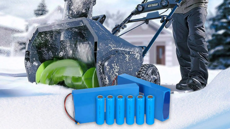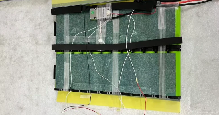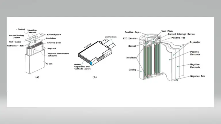
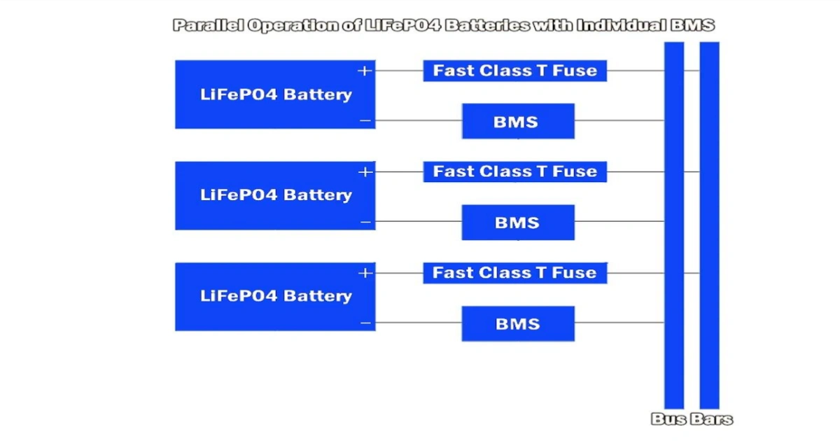
Connecting lithium battery packs in parallel is a common way to increase total battery capacity and current output while maintaining the same nominal system voltage. This configuration is widely used in energy storage systems, backup power supplies, industrial equipment, telecommunications, and other applications.
However, connecting multiple battery packs in parallel is not as simple as connecting their positive and negative terminals together. Differences in voltage, state of charge (SOC), internal resistance, cable resistance, and battery management system (BMS) characteristics can affect current distribution between packs.
If these factors are not properly evaluated, excessive circulating current, uneven loading, unexpected BMS protection events, and accelerated battery degradation may occur.
This article explains how parallel-connected battery packs work, why current sharing matters, what causes circulating current, and which design considerations help improve the safety and reliability of a parallel battery system.
1. Why Connect Lithium Battery Packs in Parallel?
Parallel connection is commonly used when a single battery pack cannot provide sufficient capacity or current for an application.
When compatible battery packs are connected in parallel:
- Nominal system voltage remains the same.
- Total rated capacity (Ah) increases.
- Available current capability may increase, depending on each pack’s specifications and operating conditions.
- Runtime can increase when the connected system operates within its specified limits.
For example, connecting two compatible 12.8V 100Ah LiFePO4 battery packs in parallel theoretically provides:
| Parameter | One Battery Pack | Two Packs in Parallel |
|---|---|---|
| Nominal Voltage | 12.8V | 12.8V |
| Rated Capacity | 100Ah | 200Ah |
| Nominal Energy | 1,280Wh | 2,560Wh |
The actual usable capacity and output current depend on the battery specifications, BMS limits, operating temperature, and system design.
Parallel connection is therefore a practical solution for applications requiring higher energy storage capacity without increasing the nominal system voltage.
For a general explanation of series and parallel battery configurations, see Battery University – BU-302: Series and Parallel Battery Configurations.
2. How Does Current Sharing Work Between Parallel Battery Packs?
When multiple battery packs are connected to the same DC bus, they share the system load.
However, current does not necessarily divide equally between the connected packs.
Current distribution depends on several factors:
- Battery pack voltage and SOC
- Internal electrical resistance
- BMS and protection circuit characteristics
- Cable length and cross-sectional area
- Connector and busbar resistance
- Battery temperature and state of health (SOH)
Consider two battery packs connected in parallel.
If both packs have similar electrical characteristics and are connected through paths with similar resistance, their current contributions may be relatively balanced.
However, if one battery pack has lower internal resistance or a shorter, lower-resistance connection path, it may supply more current than the other.
For example, under a total system load of 40A, two battery packs might supply 22A and 18A rather than exactly 20A each.
This is an illustrative example, not a universal current-sharing ratio.
Uneven current distribution can cause one battery pack to operate under greater electrical stress, potentially increasing its temperature and accelerating degradation over time.
A 2024 IEEE conference paper specifically investigated current distribution between parallel-connected lithium-ion battery packs in telecommunications applications, including the effects of pack age, capacity variation, and SOC differences.
Reference: IEEE – Analyzing Impact of Current Distribution on Parallel Connected Battery Packs in Telecom Applications.
3. What Causes Circulating Current Between Parallel Battery Packs?
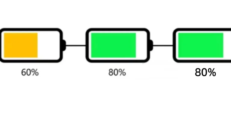
Circulating current occurs when a voltage difference exists between two or more electrically connected battery packs.
For example, consider two battery packs:
- Battery Pack A: 13.2V
- Battery Pack B: 12.8V
When these packs are directly connected in parallel, the voltage difference can drive current from the higher-voltage pack toward the lower-voltage pack.
This current flows because the two battery packs are trying to reach a common terminal voltage.
The magnitude of the initial current is influenced by:
- Voltage difference between the packs
- Internal resistance of each battery pack
- Resistance of cables and connectors
- BMS switching and protection characteristics
In a simplified electrical model, the initial current can be estimated using:
I = ΔV / R_total
Where:
- I = Initial circulating current
- ΔV = Voltage difference between battery packs
- R_total = Combined resistance of the electrical paths
For example, if the voltage difference is 0.4V and the total path resistance is 20mΩ:
I = 0.4V / 0.020Ω = 20A
This simplified calculation illustrates why even a relatively small voltage difference can produce substantial current when the overall circuit resistance is low.
Actual current may differ because of BMS behavior, voltage recovery, electrochemical characteristics, and changing circuit resistance.
Circulating current is particularly important during initial connection and can also occur under certain operating conditions when battery packs have different voltage or SOC characteristics.
Important: Never assume that a BMS will automatically prevent excessive current from flowing between parallel-connected battery packs.
4. Voltage Matching Before Connecting Battery Packs
Checking the voltage of each battery pack before parallel connection is an important safety step.
If battery packs have significantly different terminal voltages, connecting them directly may produce a high equalization current.
A suitable pre-connection evaluation should include:
1. Check battery compatibility
Use battery packs with compatible:
- Battery chemistry
- Nominal voltage
- Charging voltage
- Discharge voltage limits
- BMS specifications
- Operating temperature ranges
Different battery chemistries or incompatible charging limits should not be combined in the same parallel system.
2. Measure terminal voltage
Measure the positive and negative terminals of each battery pack using an appropriate digital multimeter.
Compare the voltage readings before making the connection.
3. Evaluate SOC and battery condition
Similar terminal voltages do not necessarily mean that two battery packs have the same SOC or SOH.
Consider their charging history, capacity, age, and operating condition.
4. Follow the manufacturer’s voltage-matching requirements
There is no single voltage-difference limit that applies to every lithium battery pack.
Some applications may specify a small allowable voltage difference, but the acceptable value depends on battery chemistry, pack design, BMS characteristics, and connection impedance.
Do not treat a general voltage difference, such as 0.05V, as a universal industry requirement.
For more information about battery open-circuit voltage measurements, see:
Tektronix – Methods to Measure Open Circuit Voltage on a Battery Pack.
5. BMS Protection and Compatibility in Parallel Battery Systems
Each lithium battery pack generally has its own Battery Management System (BMS).
The BMS monitors and protects the battery according to its design and programmed limits.
Typical protection functions include:
- Overcharge protection
- Over-discharge protection
- Overcurrent protection
- Short-circuit protection
- Temperature protection
However, when multiple independent battery packs are connected in parallel, their BMS units do not necessarily communicate or coordinate with one another.
This creates several important considerations.
Independent protection does not guarantee coordinated operation.
One battery pack may disconnect because of overcurrent or temperature protection while the remaining packs continue supplying the load.
This can suddenly increase the current carried by the remaining battery packs.
BMS compatibility matters.
Some battery systems support parallel operation, while others do not.
Certain systems require communication between battery BMS units or a central battery controller to coordinate charging, discharging, and protection.
Before connecting multiple packs, confirm that their manufacturers permit parallel operation and specify the required BMS configuration.
Pack-level current monitoring is useful.
Monitoring the current of each battery branch helps identify uneven loading and abnormal operating conditions.
For larger systems, a central monitoring or control system may be necessary.
6. Four Common Mistakes When Connecting Battery Packs in Parallel
Mistake 1: Connecting Battery Packs with Different Voltage Levels
Connecting battery packs with significantly different terminal voltages can generate excessive initial equalization current.
Always check voltage compatibility and follow the manufacturer’s connection procedure.
Mistake 2: Using Unequal Cable Lengths and Resistance
Different cable lengths, cross-sectional areas, connectors, and contact resistances can create different electrical paths.
As a result, one battery pack may carry more current than another.
Using appropriately sized cables with symmetrical connection paths can help improve current distribution.
However, equal cable length alone does not guarantee perfectly balanced current.
Mistake 3: Assuming Every BMS Supports Parallel Operation
Not all battery management systems are designed for multiple battery packs connected in parallel.
Protection thresholds, charge and discharge limits, communication protocols, and MOSFET control strategies may differ.
Always confirm parallel-operation compatibility before connecting independent battery packs.
Mistake 4: Ignoring Individual Branch Protection
A parallel battery system should be designed with appropriate overcurrent protection for each battery branch.
Depending on the system architecture, this may include individual fuses or DC circuit breakers.
Protection devices must be selected according to the battery’s maximum current, cable ampacity, prospective short-circuit current, DC voltage rating, and applicable safety requirements.
A properly designed protection system helps isolate a faulty branch and reduces the risk of damage to other connected equipment.
7. Best Practices for Safe Parallel Battery Connections
Before commissioning a parallel battery system, consider the following checklist:
| Item | Recommended Practice |
|---|---|
| Battery chemistry | Use compatible battery chemistry |
| Nominal voltage | Use compatible voltage ratings |
| Battery condition | Evaluate SOC, SOH, and capacity |
| Voltage matching | Follow manufacturer requirements |
| BMS compatibility | Confirm parallel-operation support |
| Cable configuration | Use appropriately sized, symmetrical paths |
| Branch protection | Provide suitable independent overcurrent protection |
| Current monitoring | Monitor individual battery branch currents |
| System commissioning | Follow the manufacturer’s connection procedure |
For larger battery systems, a qualified electrical engineer should evaluate the busbar design, protection coordination, fault current, thermal conditions, and BMS communication requirements.
Parallel connection should never be treated as a simple wiring modification without considering the complete electrical system.
Conclusion
Connecting lithium battery packs in parallel is an effective way to increase system capacity while maintaining the same nominal voltage.
However, reliable operation depends on more than simply connecting positive terminals together and negative terminals together.
Voltage compatibility, current sharing, circulating current, cable resistance, branch protection, and BMS coordination all play important roles in system performance and safety.
Understanding these factors helps engineers and system integrators develop more reliable parallel battery configurations for industrial equipment, backup power, energy storage, and other applications.
For customized lithium battery pack projects, selecting the appropriate cell configuration, BMS protection, wiring, and electrical specifications at the design stage is essential.
Need a Customized Lithium Battery Pack Solution?
LNC Batteries supports customized lithium-ion battery pack solutions for different voltage, capacity, current, dimension, connector, and BMS requirements.
Whether you are developing a new product or evaluating a battery solution for an existing application, our team can help assess your requirements and coordinate suitable battery pack development.
Explore our Custom Lithium-ion Battery Pack Solutions or contact LNC Batteries to discuss your project.
Technical References
- IEEE – Analyzing Impact of Current Distribution on Parallel Connected Battery Packs in Telecom Applications (2024)
- Tektronix – Methods to Measure Open Circuit Voltage on a Battery Pack
- Battery University – BU-302: Series and Parallel Battery Configurations
Disclaimer: This article is intended for general technical education. Actual parallel battery configurations must follow the battery manufacturer’s specifications, BMS requirements, and applicable electrical safety standards. The simplified calculations and examples in this article should not replace a detailed engineering assessment.