MOSFETs are essential components in lithium battery management systems (BMS). They control the charging and discharging paths and help protect battery packs against abnormal operating conditions.
However, selecting a MOSFET for a BMS involves more than checking its maximum current rating.
In practical applications, MOSFETs may experience different types of electrical and thermal stress. For example:
- An electric bicycle battery may overheat its MOSFETs during continuous high-current operation.
- A battery pack used in an energy storage system may experience MOSFET damage during short-circuit testing.
- A power tool battery may encounter high current during motor startup or a locked-rotor condition.
These situations involve different operating conditions and require different evaluation methods.
This article explains three important aspects of BMS MOSFET selection: continuous current, pulse current, and short-circuit protection.
1. What Do MOSFETs Do in a BMS?
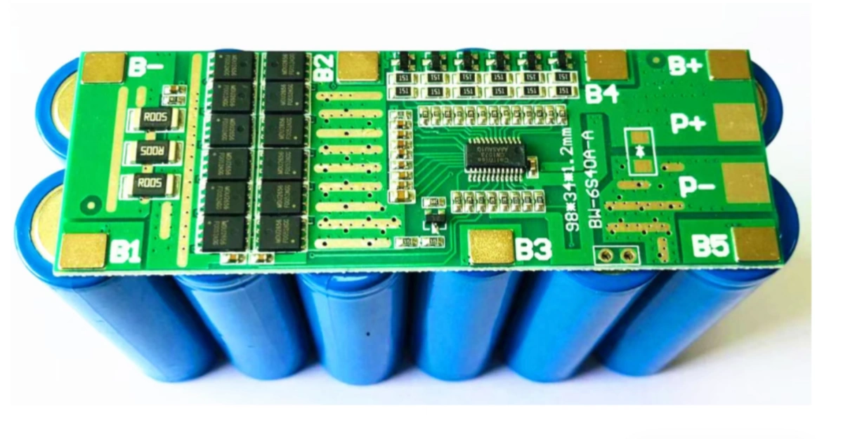
In many lithium battery protection circuits, MOSFETs act as electronic switches controlling the charging and discharging paths.
When the battery operates normally, the MOSFETs remain switched on, allowing current to flow.
When the protection circuit detects an abnormal condition, such as overcurrent, short circuit, overcharge, or over-discharge, the protection IC can control the MOSFET gates to interrupt the current path.
Many battery protection designs use two MOSFETs connected back-to-back. Common configurations include common-source and common-drain arrangements.
The actual configuration depends on the circuit design.
Because MOSFETs carry the battery current and must interrupt abnormal current conditions, their selection directly affects the electrical and thermal performance of the BMS.
2. First Challenge: Continuous Current and Thermal Management
Continuous current is one of the most important factors when selecting MOSFETs.
When a MOSFET is switched on, it has a certain resistance between its drain and source terminals. This is called on-state resistance, commonly written as RDS(on).
Current flowing through this resistance generates heat.
The conduction loss can be estimated using:
Power Loss = Current x Current x On-State Resistance
For example, consider a BMS using two MOSFETs connected in series in the current path.
Assume:
- Continuous current: 15 A
- On-state resistance of each MOSFET: 2 milliohms
- Total resistance: 4 milliohms
The estimated total conduction loss is:
15 x 15 x 0.004 = 0.9 W
If both MOSFETs have the same resistance and carry the same current, each MOSFET dissipates approximately 0.45 W.
This is a simplified calculation. Actual power loss also depends on the MOSFET operating temperature, gate voltage, switching behavior, and circuit layout.
Why Is Temperature Important?
MOSFET on-state resistance generally increases as junction temperature rises.
Higher resistance produces more heat, which can further increase the junction temperature.
Therefore, MOSFET selection should not rely only on the resistance value specified at 25°C.
Engineers should check the RDS(on) temperature characteristics in the manufacturer’s datasheet and evaluate the MOSFET under the expected operating conditions.
PCB Design Also Matters
The MOSFET’s thermal performance depends heavily on the PCB design.
Important factors include:
- PCB copper area and copper thickness
- Thermal vias and copper planes
- PCB material and thickness
- Component placement and spacing
- Ambient temperature
- Airflow and heat dissipation conditions
The thermal resistance value listed in a MOSFET datasheet is measured under specific test conditions. It should not automatically be treated as the thermal resistance of the actual BMS assembly.
A simplified steady-state temperature estimate is:
Junction Temperature = Ambient Temperature + Power Loss x Thermal Resistance
Here, junction temperature means the internal operating temperature of the MOSFET semiconductor.
For short-duration events, transient thermal impedance should also be considered because the temperature does not rise instantaneously.
The key point is that a MOSFET with a high current rating does not necessarily operate safely at that current in every PCB design.
3. Second Challenge: Pulse Current and Safe Operating Area (SOA)
Battery applications often involve temporary current peaks.
Examples include:
- Electric motor startup
- Power tool acceleration
- Motor stall or locked-rotor conditions
- Short-duration load surges
A MOSFET may tolerate a high current for a short period, even when that current is higher than its continuous operating current.
However, the allowable pulse current depends on the operating conditions.
Peak Current Rating Is Not Enough
The maximum pulsed drain current shown in a datasheet should not be treated as a universal guarantee.
Its applicability depends on factors such as:
- Pulse duration
- Duty cycle and repetition frequency
- Initial junction temperature
- Case temperature
- PCB thermal conditions
- Gate-source voltage
Repeated pulses can cause heat accumulation. A MOSFET that tolerates one short pulse may not tolerate the same pulse repeated continuously.
Understanding the Safe Operating Area (SOA)
The Safe Operating Area, or SOA, describes the combinations of drain-source voltage and drain current that a MOSFET can withstand under specified conditions.
It is particularly important when the MOSFET operates with both significant voltage across it and current flowing through it.
For example, during switching transitions or certain abnormal operating conditions, the MOSFET may temporarily operate outside its fully enhanced, low-resistance state.
In these situations, engineers must check the SOA curves in the manufacturer’s datasheet.
The evaluation must consider the specified pulse duration, case temperature, gate voltage, and other test conditions.
There is no universal rule that every MOSFET must have exactly twice the calculated SOA margin. The appropriate design margin depends on the actual application and operating conditions.
It is also important to distinguish between two situations:
- High current while fully switched on: Evaluate on-state resistance, conduction loss, transient thermal behavior, and pulse ratings.
- High current with significant voltage across the MOSFET: Evaluate the SOA and the MOSFET’s ability to withstand the operating point.
These are different electrical stresses and should not be evaluated using the same method.
4. Third Challenge: Short-Circuit Protection
Short-circuit conditions can create extremely high current within a very short time.
This is one of the most demanding conditions for a BMS MOSFET.
When a short circuit occurs, the protection IC must detect the abnormal current and control the MOSFETs to interrupt the current path.
However, the MOSFET does not turn off instantaneously.
The total interruption time depends on several factors:
- Protection IC detection threshold
- Detection filtering and delay
- IC propagation delay
- Gate discharge characteristics
- MOSFET gate charge
- External circuit components and layout
Different protection ICs have different response characteristics. The actual protection delay must be checked against the selected IC datasheet and circuit configuration.
Short-Circuit Current Depends on the Entire System
It is not possible to calculate the actual short-circuit current from battery voltage and capacity alone.
For example, a 48 V, 20 Ah battery pack does not have one fixed short-circuit current value.
The actual current depends on:
- Cell internal resistance
- Number of cells connected in parallel
- Battery state of charge
- Cell temperature
- Busbar and wiring resistance
- Connector and contact resistance
- Protection circuit resistance
Therefore, short-circuit current should be evaluated using the actual battery configuration and relevant test data.
MOSFET Stress During Turn-Off
When the protection circuit interrupts a large current, parasitic inductance in the wiring and PCB can generate a voltage spike.
This voltage may appear across the MOSFET during turn-off.
If the voltage exceeds the device’s limits, the MOSFET may enter avalanche breakdown or suffer damage.
Engineers should therefore evaluate:
- MOSFET voltage rating
- Turn-off voltage spikes
- Safe Operating Area
- Avalanche capability, where applicable
- TVS or other voltage-clamping components
- PCB layout and wiring inductance
Avalanche capability should not be assumed simply because a MOSFET datasheet contains an avalanche rating. The actual current, pulse duration, starting temperature, and repetitive operating conditions must remain within the manufacturer’s specifications.
A suitable protection design must coordinate the protection IC, MOSFETs, and surrounding circuit components.
5. Practical Example: Evaluating MOSFETs for a 48 V Battery Pack
Consider a hypothetical 48 V lithium battery pack with the following requirements:
| Parameter | Example Value |
|---|---|
| Battery configuration | 13S lithium-ion |
| Nominal voltage | 46.8 V |
| Maximum charging voltage | 54.6 V |
| Continuous discharge current | 15 A |
| Temporary overload current | 45 A |
| Overload duration | 100 ms |
| Short-circuit current | To be determined from actual system impedance |
This example is intended to illustrate the evaluation process. It does not represent a verified MOSFET selection.
Step 1: Check Continuous Current
Calculate the total MOSFET conduction loss using the on-state resistance at the expected operating temperature.
Then evaluate whether the actual PCB can dissipate the generated heat while keeping the junction temperature within the MOSFET’s specified limits.
Step 2: Check Pulse Current
For the 45 A, 100 ms overload condition, check the MOSFET datasheet and evaluate the pulse operating conditions.
If the MOSFET remains fully enhanced, consider its on-state resistance and transient thermal impedance.
If significant voltage appears across the MOSFET during the event, check whether the operating point remains within the applicable SOA curve.
Also consider whether the overload can occur repeatedly.
Step 3: Check Short-Circuit Protection
Determine the expected short-circuit current based on the actual battery pack impedance and circuit resistance.
Then verify whether the protection IC can detect and interrupt the fault within the required time.
Finally, evaluate MOSFET voltage stress during turn-off, including possible voltage spikes caused by parasitic inductance.
Step 4: Verify the Complete Protection Circuit
MOSFET selection cannot be separated from the overall BMS design.
The protection IC, MOSFETs, PCB layout, wiring, and voltage-clamping components must work together.
Actual testing is necessary to verify the design under the intended operating conditions.
6. Common Mistakes When Selecting BMS MOSFETs
Several common mistakes can lead to MOSFET overheating or premature failure.
Mistake 1: Selecting MOSFETs only by their maximum current rating
The current rating in a datasheet is based on specified test conditions. Actual performance depends on thermal design, PCB layout, and operating temperature.
Mistake 2: Ignoring the temperature dependence of on-state resistance
The resistance value at 25°C may be significantly lower than the value at the actual operating temperature.
Mistake 3: Using peak current ratings without checking pulse duration
A peak current rating does not automatically mean the MOSFET can withstand that current under every pulse duration or repetition frequency.
Mistake 4: Ignoring the Safe Operating Area
When the MOSFET operates with significant voltage and current simultaneously, checking only the maximum current rating is insufficient.
Mistake 5: Assuming the protection IC response time is the complete turn-off time
The actual interruption time also depends on gate discharge and the surrounding circuit.
Mistake 6: Ignoring voltage spikes during turn-off
Parasitic inductance can generate voltage spikes that may exceed the MOSFET’s voltage rating.
7. A Practical Checklist for BMS MOSFET Selection
Before selecting MOSFETs for a lithium battery protection circuit, engineers should review the following items:
- Confirm the battery’s nominal voltage and maximum charging voltage.
- Determine the required continuous discharge current.
- Identify temporary overload current and pulse duration.
- Check MOSFET on-state resistance at the expected operating temperature.
- Calculate conduction losses for the complete MOSFET current path.
- Evaluate PCB thermal performance.
- Check transient thermal impedance for pulsed operation.
- Review the SOA curves under the actual operating conditions.
- Confirm the protection IC’s detection threshold and response characteristics.
- Evaluate short-circuit interruption and turn-off voltage spikes.
- Verify the design through appropriate electrical and thermal testing.
Conclusion
Selecting MOSFETs for a lithium battery BMS requires more than comparing current ratings.
Continuous current mainly involves conduction loss and thermal management. Pulse current requires evaluation of pulse duration, thermal accumulation, and the Safe Operating Area. Short-circuit protection requires coordination between the protection IC, MOSFET switching behavior, and the overall circuit design.
A reliable BMS design must consider all three operating conditions together.
At LNC Batteries, we support lithium battery cell supply and customized battery pack assembly solutions for different applications. Our team works with manufacturing partners to evaluate battery pack requirements, protection functions, and assembly specifications.
If you are developing a customized lithium battery pack and need support with cell selection or pack assembly, please contact our team.
Technical References
- Infineon – Designing with Power MOSFETs
- Infineon – Linear Mode Operation and Safe Operating Diagram of Power MOSFETs
- Nexperia – Thermal Boundary Condition Study on MOSFET Packages and PCB Substrates
- Nexperia – MOSFETs in Power Switch Applications
- Texas Instruments – BQ76952 Battery Monitor and Protector Datasheet